


Diode bridge rectifier
Bridge rectifier, namely bridge rectifier, also known as rectifier bridge, is the most commonly used circuit that uses the unidirectional continuity of the diode for rectification, and is often used to convert alternating current into direct current.
Principle
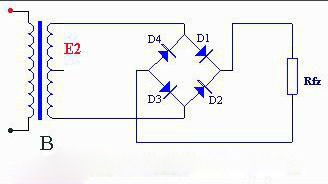
The working principle of bridge rectifier circuit is as follows: when E2 is positive half cycle, apply forward voltage to D1 and D3, and D1 and D3 are on; Apply reverse voltage to D2 and D4, and D2 and D4 are disconnected. E2, D1, Rfz and D3 power-on circuits are formed in the circuit, and the upper positive and lower negative half-wave rectification voltages are formed on Rfz. When E2 is negative half cycle, the forward voltage is applied to D2 and D4, and D2 and D4 are connected; Apply reverse voltage to D1 and D3, and D1 and D3 are disconnected. E2, D2, Rfz and D4 power-on circuits are formed in the circuit, and positive and negative half-wave rectification voltage is also formed on Rfz. Repeat this operation, and the result is the full-wave rectification voltage at Rfz. Its waveform is the same as that of full-wave rectification. It is not difficult to see from the figure that the reverse voltage borne by each diode in the bridge circuit is equal to the maximum secondary voltage of the transformer, which is half smaller than the full-wave rectifier circuit.
Effect
Bridge rectification is an improvement of diode half-wave rectification.
Half-wave rectification uses the unidirectional conduction characteristics of diodes. When the input is a standard sine wave, the positive half of the sine wave is obtained and the negative half is lost.
The bridge rectifier uses four diodes to connect with each other. The positive half of the input sine wave is connected by two tubes to obtain positive output; When inputting the negative half of the sine wave, connect the other two tubes. Because the two tubes are connected in reverse, the output is still the positive half of the sine wave. The utilization efficiency of the bridge rectifier for the input sine wave is twice that of the half-wave rectifier. Bridge rectification is the first step to convert AC to DC.
The bridge rectifier is composed of a plurality of rectifier diodes connected by a bridge and sealed with insulating plastic. The high-power bridge rectifier is sealed with a metal shell outside the insulation layer to enhance heat dissipation. There are many types of bridge rectifiers with excellent performance, high rectification efficiency and good stability. The maximum rectifier current is 0.5A to 50A, and the maximum reverse peak voltage is 50V to 1000V.
Filter voltage stabilization
After rectification, a filter is often added to stabilize the voltage. The filter circuit will change the pulse ratio of the rectifier output, which is related to the load. Therefore, the voltage obtained after final rectification is not only related to the rectification mode, but also related to the load and filter capacitance. Therefore, the selection of filter capacitance is not random, but needs to select the appropriate value according to the load.
After connecting the filter circuit, the average output voltage is about 1.2 times and the load open circuit is 1.414 times.